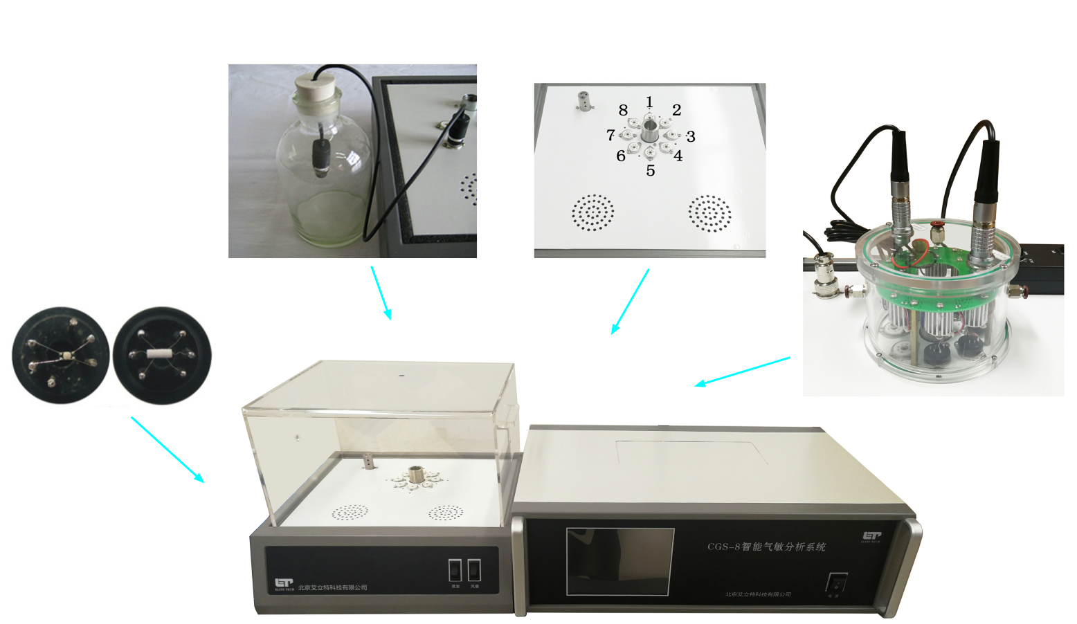
GS-8 intelligent gas sensitive analysis system (resistance type), which is composed of data acquisition system, heating system, gas distribution system and test software. CGS-8 intelligent gas sensitive analysis system can measure the gas sensitive characteristics of resistive side heating gas sensor, the system controls the working temperature by adjusting the heating current, and has the characteristics of complete independence of each channel, large resistance (Rg) measurement range, large heating current adjustment range, multiple sensitivity types can be selected, touch screen control, real-time temperature and humidity monitoring, etc. The system communicates with the computer through the USB interface, collects the data in real time, and can directly analyze the characteristics of the sensor sensitivity. CGS-8 intelligent gas sensitive analysis system is used for gas sensitive analysis of various powder/particle materials.
Product features
01) Independent control of each channel heating current, one-time measurement of the device at different temperatures, easy to find the best working conditions
02) Large measurement range, can measure a variety of resistivity range of gas sensitive materials
03) Large heating current range, can be used for a variety of micro and nano gas sensors
04) Anti-leakage gas injection design, eliminate leakage during gas injection, improve the precision of gas distribution
05) Real-time monitoring of air chamber temperature and humidity to improve experimental accuracy and repeatability
06) The software realizes real-time acquisition and reality of gas sensitive characteristics such as resistance value, sensitivity (Ra/Rg, Rg/Ra, | ra-Rg |/Ra), maximum value and minimum value, and supports logarithmic coordinate display to accurately reflect signal changes between multiple orders of magnitude of the device
Technical index
01) Power supply: AC 220 V, Max power 100 W
02) Number of test channels: 8, completely independent
03) Heating current: DC 0~400 mA continuous adjustable, accuracy 1 mA, 8 separate control
04) Measuring range: 1Ω ~ 500MΩ, automatic measurement without shifting
05) Acquisition interval: ≥100ms, continuously adjustable
06) Collection time limit: >1 s, continuously adjustable
07) Air box temperature and humidity monitoring
08) 2 air injection ports, 1 liquid injection port
09) Communication interface: USB
10) Control mode: 8 inch touch screen
11) Supporting host computer analysis software, providing software technical support
12) Overall dimensions of the main machine: 600 mm × 400 mm × 200 mm; Overall dimensions of air tank base: 410 mm × 390 mm × 120 mm; Gas box (glass material) overall size: 360 mm × 330 mm × 220 mm; Air tank volume: 20 L
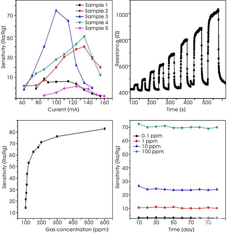
13) Sensitivity current analysis, response recovery analysis, sensitivity concentration analysis, selectivity analysis, stability analysis, etc
Matters needing attention
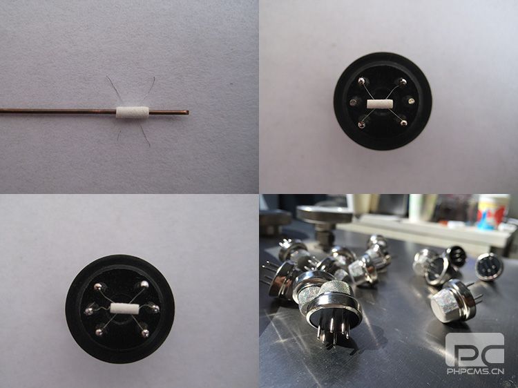
01) This analysis system needs to produce side-heating gas sensor for testing, please use side-heating sensor accessories (see side-heating sensor accessories description page);
02) This analysis system is only for the test of indirect heat gas sensor, do not use direct heat structure gas sensor;
03) The heating current should be set appropriately according to the sensor to avoid burning the heating wire, for about 35 Ω Ni-Cr heating wire, the current should not exceed 250 mA;
04) When measuring large resistance (>100MΩ), it is necessary to connect 4 signal electrodes according to the sensor structure, otherwise the measured resistance value will be affected by the electric field generated by the heating current, and please pay attention to eliminate the interference of external electric field or magnetic field;
05) The device usually needs to be aging to be stable, it is recommended to use AS-20 sensor aging table;
06) The coating process of device fabrication may affect the morphology and structure of the material. This analysis system is mainly suitable for gas sensitive analysis of various powders and particle materials. For gas-sensitive materials with special morphology and structure, the device fabrication process involved in this analysis system may reduce the gas-sensitive properties of some materials.
System photo
Typical result
appendix
1) Gas distribution instructions
Gas distribution
According to the formula Q = C × V gas distribution
Where: Q is the volume of gas (mL) to be taken; C is the concentration of the gas to be prepared (ppm); V is the test bottle volume (mL).
For example, for a 1000 mL gas cylinder, configure 1000 ppm gas:
Q = 1000 × 1000 × 10-6 = 1 mL
That is, it is necessary to take 1 mL of gas and inject it into a 1000 mL gas cylinder.
When using cylinders (tanks) with different volumes, enlarge or reduce the volume of the required gas according to the volume ratio (for example, the volume of the gas required to be injected is 20 mL when the 20 L gas tank is configured with 1000 ppm gas).
Liquid gas distribution
According to the formula Q = (V × C × M)/(22.4 × d × ρ) × 10-9 × (273 + TR)/(273 + TB) gas distribution
Where: Q is the volume of liquid (mL) to be taken; V is the volume of the test bottle (mL); M is the molecular weight of the substance (g); ρ is the purity of the liquid; C is the concentration of the gas to be prepared (ppm); d is the liquid density (g/cm3); TR is the test ambient temperature (°C); TB is the temperature (°C) inside the test bottle.
For example, ethanol gas is configured with anhydrous ethanol, and 1000 ppm ethanol gas is configured for 1000 mL cylinders:
Q = (1000 × 100 × 46)/(22.4 × 0.79) × 10-9 = 0.0026 mL = 2.6 μL
It is necessary to take 2.6 μL of anhydrous ethanol and inject it into 1000 mL gas cylinder and volatilize.
When using gas cylinders (tanks) with different volumes, enlarge or reduce the volume of the required liquid according to the volume ratio (for example, the volume of the liquid required to be injected is 58 μL when the 20 L tank is configured with 1000 ppm ethanol gas).
Note: ppm stands for 10-6, ppb stands for 10-9, ppt stands for 10-12